 If there’s anything that we’ve learned in 30+ years of business, it’s that our customers are smart. Often, you’re the best in your field. You know your industry as well as you know the face looking back at you in the mirror.
And you know exactly what you need from a viscometer.
The challenge lies in knowing what viscometer manufacturers offer, and how many boxes different viscometers check on your needs/wants/nice-to-have list.
We get it. And because our job is to reduce your challenges, we created an easy-to-use, 7-step configuration guide to help you figure out how to configure your Cambridge Viscosity VISCOpro 2100 viscometer.
It’s a simple process, but we’ll walk you through it. First, we recommend printing it out.
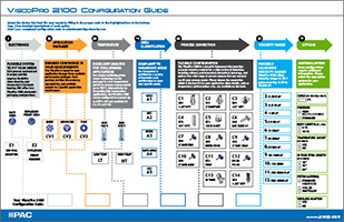
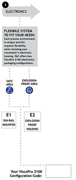
Section 1: Electronics
The first step is to select your electronics configuration. You have 2 options. If you’re in a safe area, like a lab, you’ll probably select E1, DIN-Rail Mounted. Write “E1” in the gray box
If you work in an explosion-proof area, you’ll need explosion-proof housing. Write “E2” in the gray box.
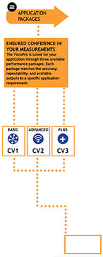
Section 2: Application Packages
We have three available performance packages – Basic (or Core), Advanced, and Plus. If you look at page 2 on the configuration guide, we’ve provided some additional features of each option so you can select the level that is best for your specific application. Write CV1, CV2, or CV3 in the orange box as appropriate.
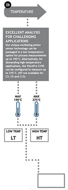 Section 3: Temperature
The VISCOpro 2100 can be configured to meet your specific temperature requirements. Our low-temp option is for applications that have a maximum temperature of 190 °C, while our high temperature option has a maximum temperature of 375 °C.
We’re going to jump ahead for just a minute, because your choice of high or low-temperature viscometer will impact the sensors you can select. In Section 5, you’ll be able to choose your process connection. High temperature options include C1, C2, C6, C7, C8, C9, C10, C11, C12 and C14. Write your section in the medium gray box.
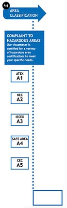 Section 4: Area Classification
The VISCOpro 2100 is compliant with many hazardous area certifications. Section 4 allows you to specify if any of those classifications is a requirement for your viscometer. You can select from ATEX (A1), NEC (A2), IECEX (A3), Safe Area (A4), or CEC (A5). Write your selection in the royal blue box.
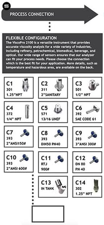
Section 5: Process Connection
Section 5 is probably the section you’ll give the most thought to – this is where you select your sensor. The 2nd page of the configuration guide offers further detail on each option. We’ve developed a wide range of sensors to meet the varying needs of our customers and varying piping specifications. For example, if you selected a high-temperature viscometer, your best options are C1, C2, C6, C7, C8, C9, C10, C11, C12, and C14. Occasionally, we come across applications that require a custom configuration. If this is the case for you, feel free to reach out to our application engineers to talk shop and determine what you need. Otherwise, write your selection (C1-C14) in the dark gray box.
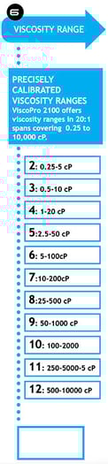 Section 6: Viscosity Range
The VISCOpro 2100 offers viscosity ranges in 20:1 spans covering 0.25 to 10,000 cP. For section 6, write your required viscosity range section (2-12) in the light blue box.
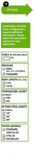 Section 7: Options
This section allows you to further customize your viscometer by selecting a few options, such as a longer cable, high or standard pressure, body length, temperature jacket, in-tank stem length, or piston material. Check the boxes as necessary, and ignore the ones that don’t apply to your application.
You’re done! The completed guide will generate a code, for example, E1-CV3-LT-A4-C4-7. Just email the completed form, or even just this code, to sales@cambridgeviscosity.com, and we’ll call you back within 24 hours to discuss your viscometer further. (You can send the completed pdf, or if you wrote it out by hand, just snap a photo.)